For 300 GHz-class antennas, wavelengths drop below 1 mm and conventional far-field measurement quickly hits walls of range, environment, and cost. We overcome them with near-field measurement using metal-free micro EO (electro-optic) sensor probes. The amplitude and phase distribution over the antenna aperture can be measured in a compact setup, capturing what far-field measurement cannot: how each part of the antenna actually behaves. Frequency coverage is 1 GHz to 330 GHz. Because our photonics-based system needs no VNA or frequency extenders, it is particularly cost-competitive above 100 GHz. The technology was matured under a NICT Beyond 5G commissioned research program and is available as an antenna near-field measurement system.
Measure the field as it is, without disturbing it — measurement that only photonics can deliver.
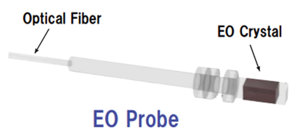
The probe consists of an EO crystal on the tip of an optical fiber — an all-dielectric structure containing no metal — and detects the electric field directly. Unlike metal probes, it hardly disturbs the field under test, so even in the 300 GHz band, where wavelengths are sub-millimeter, it achieves both spatial resolution and non-invasiveness. Its extremely light weight lets it ride on a simple robot arm, keeping the entire measurement environment compact.
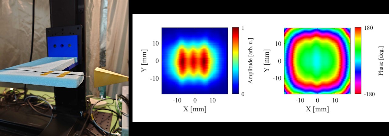
Far-field measurement gives you only the synthesized pattern; near-field measurement shows the amplitude and phase distribution over the aperture itself. Because the EO probe is non-invasive to the field, you obtain simulation-like amplitude/phase maps even right next to the antenna, and can directly verify that the antenna is excited as designed. Near-field-to-far-field transformation software also yields radiation patterns and gain.
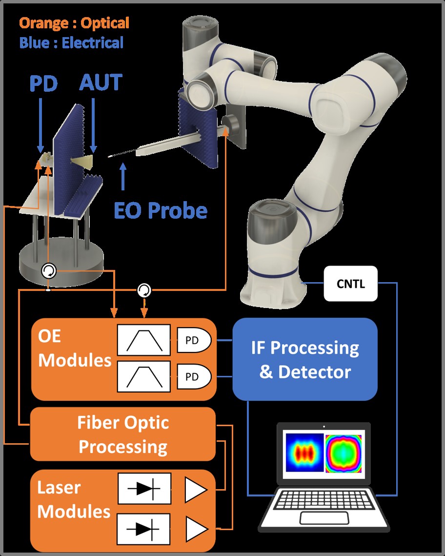
No long far-field range is needed, and the measurement core (AUT plus EO probe) is routed by optical fiber, so the system fits in an existing anechoic chamber, a small anechoic box, or a simple shielded tent in your lab. Probe scanning is performed by a robot arm, supporting planar, cylindrical, and spherical scans. Available both as a system for purchase and as a contract measurement service.
| Frequency | 1 GHz – 330 GHz. Band changed/extended by swapping the Tx photodiode module (1–70 GHz / W-band / D-band / J-band) |
|---|---|
| Method | Proprietary photonics-based system; no VNA or extenders required |
| Scanning | Planar, cylindrical, and spherical scans by robot arm |
| Output | Near-field amplitude/phase distributions; NF–FF transformation software (radiation pattern, gain) |
| Installation | Existing chamber / small anechoic box / simple shielded tent (proposals available) |
| Delivery | Measurement system sales / contract measurement |
From 300 GHz-band measurements to element-level diagnosis in the extreme near field — real examples with the current system.
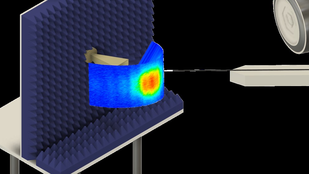
A 300 GHz-band gain horn antenna was measured by cylindrical near-field scanning and transformed to the far field. The transformed radiation pattern agrees well with simulation, demonstrating that the near-field-measurement-to-far-field-transformation flow works at a practical level even in the sub-terahertz band.
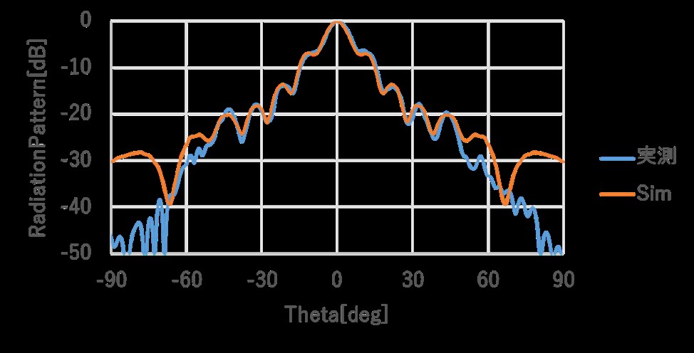
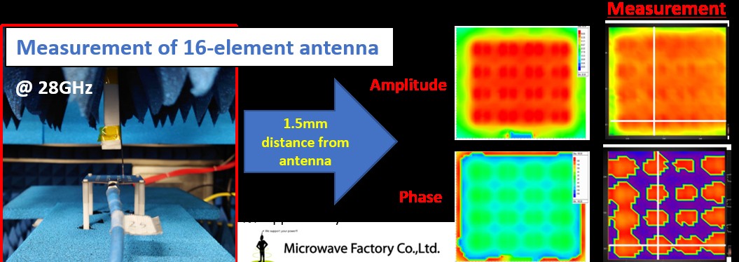
A 28 GHz, 16-element patch antenna was measured just 1.5 mm from the antenna surface. The amplitude and phase of each individual element can be evaluated, with measured results agreeing well with simulation. This enables evaluations impossible with far-field measurement, such as array-excitation diagnosis and identification of faulty elements.
Matured through a national R&D program, and already used for third-party sub-terahertz antenna evaluations.
Commissioned research (seed-creation program) that developed and put into practice compact sub-terahertz antenna evaluation based on EO-probe near-field measurement, carried out jointly with a partner company.
Contract R&D, custom measurement instruments, software development, joint research — we work in whatever form suits your project.
Contact Us